Let's learn, share & inspire each other. Sign up now 🤘🏼
Let's learn, share & inspire each other. Sign up now 🤘🏼
 ARTICLE
 4 min read
Binary Phase Shift Keying ( BPSK )
Phase Shift Keying (PSK) is the digital modulation technique in which the phase of the carrier signal is changed by varying the sine and cosine inputs at a particular time. PSK technique is widely used for wireless LANs, bio-metric, contactless operations, along with RFID and Bluetooth communications.
Any digital modulation scheme uses a finite number of distinct signals to represent digital data. PSK uses a finite number of phases, each assigned a unique pattern of binary digits. Usually, each phase encodes an equal number of bits. Each pattern of bits forms the symbol that is represented by the particular phase. The demodulator, which is designed specifically for the symbol-set used by the modulator, determines the phase of the received signal and maps it back to the symbol it represents, thus recovering the original data. This requires the receiver to be able to compare the phase of the received signal to a reference signal – such a system is termed coherent (and referred to as CPSK).
PSK is of two types, depending upon the phases the signal gets shifted. They are −
Binary Phase Shift Keying ( BPSK )
This is also called as 2-phase PSK or Phase Reversal Keying. In this technique, the sine wave carrier takes two phase reversals such as 0° and 180°.
BPSK is basically a Double Side Band Suppressed Carrier (DSBSC) modulation scheme, for message being the digital information.
Quadrature
Phase Shift Keying ( QPSK )
This is the phase shift keying technique, in which the sine wave carrier takes four phase reversals such as 0°, 90°, 180°, and 270°.
If this kind of techniques are further extended, PSK can be done by eight or sixteen values also, depending upon the requirement.
BPSK Modulator
The block diagram of Binary Phase Shift Keying consists of the balance modulator which has the carrier sine wave as one input and the binary sequence as the other input. 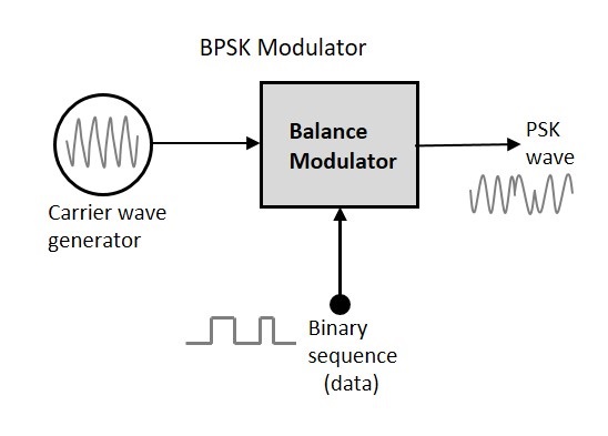
The modulation of BPSK is done using a balance modulator, which multiplies the two signals applied at the input. For a zero binary input, the phase will be 0° and for a high input, the phase reversal is of 180°.
Following is the diagrammatic representation of BPSK Modulated output wave along with its given input.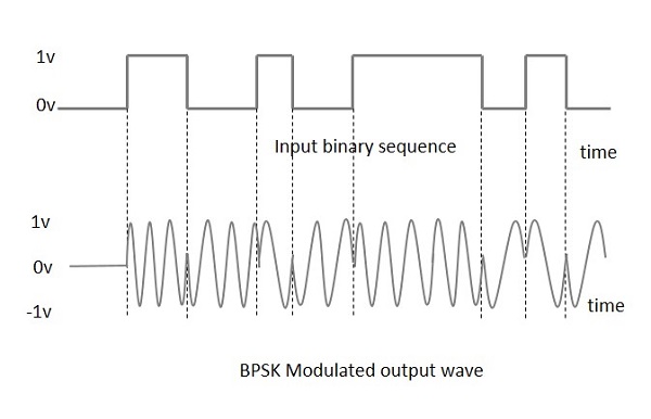
The output sine wave of the modulator will be the direct input carrier or the inverted (180° phase shifted) input carrier, which is a function of the data signal.
BPSK demodulator
The block diagram of BPSK demodulator consists of a mixer with local oscillator circuit, a bandpass filter, a two-input detector circuit. The diagram is as follows.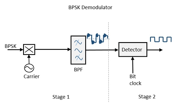
By recovering the band-limited message signal, with the help of the mixer circuit and the band pass filter, the first stage of demodulation gets completed. The base band signal which is band limited is obtained and this signal is used to regenerate the binary message bit stream.
Applications:
Owing to PSK's simplicity, particularly when compared with its competitor quadrature amplitude modulation, it is widely used in existing technologies.
The wireless LAN standard, uses a variety of different PSKs depending on the data rate required. At the basic rate of 1 Mbit/s, it uses DBPSK (differential BPSK).
Because of its simplicity, BPSK is appropriate for low-cost passive transmitters, and is used in RFID standards which has been adopted for biometric passports, credit cards, and many other applications.
Both QPSK and 8PSK are widely used in satellite broadcasting. QPSK is still widely used in the streaming of SD satellite channels and some HD channels. High definition programming is delivered almost exclusively in 8PSK due to the higher bitrates of HD video and the high cost of satellite bandwidth.
The chipsets used in new satellite set top boxes,support 8PSK and are backward compatible with the older standard.
Groups
More like this
What is Across The Globe (ATG) and What do we do?
512 Views, 8 inspired

MARKETING COMMUNICATIONS STRATEGY
88 Views, 1 inspired

Business Quote
56 Views, 2 inspired

Social Media Marketing
45 Views, 0 inspired

ATtiny85 microcontroller circuit board production
117 Views, 2 inspired

Summer Internship | Students Internship Opportunities
342 Views, 9 inspired

HR Internship Training
257 Views, 4 inspired

INTERNSHIP ALERT
97 Views, 1 inspired

Opportunity awaits ❤️ grab it soon❤️
284 Views, 3 inspired

GAOTek.Inc is hiring!
53 Views, 3 inspired

GAOTek.Inc is hiring
64 Views, 2 inspired
InnerworkIndia is hiring!
67 Views, 3 inspired
Internship in "Youngpreneours India"
43 Views, 2 inspired
HR internship at GAO Tek
439 Views, 4 inspired
customer support excutive job for smartbiz
81 Views, 2 inspired
Paid Internship
394 Views, 4 inspired

Artificial Intelligence in Healthcare.
114 Views, 4 inspired

Business development associate - Job | ATG
112 Views, 4 inspired
#Aashman Foundation
659 Views, 5 inspired

#Aashman foundation
654 Views, 1 inspired

Feedback: Introduction to recommendation system
59 Views, 0 inspired


 Comment


